
Flyback Converter Calculator
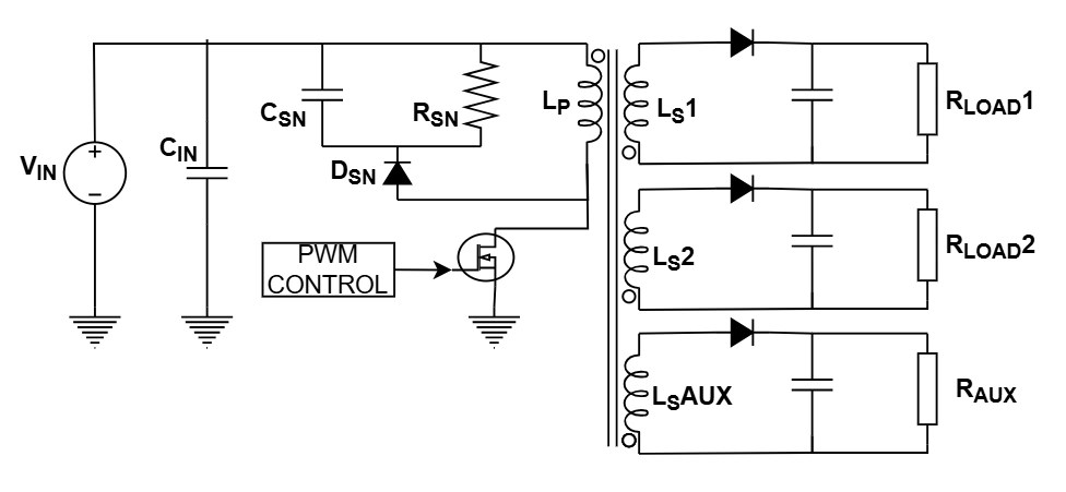
This advanced tool designs DCM Flyback Converters with multiple outputs. It calculates the primary inductance (Lp), transformer turns ratios (Np:Ns), and RCD Snubber values.
Ideal for designing offline SMPS, LED drivers, or auxiliary power supplies with 12V/5V rails and bias windings.
System Specs
Configuration| Rail | Vout | Iout | Vdrop |
|---|
Design Analysis
DCM ModeOutput Winding Details
DCM vs CCM Flyback Mode
Choosing between Discontinuous Conduction Mode (DCM) and Continuous Conduction Mode (CCM) affects efficiency and stability.
| Feature | DCM (Discontinuous) | CCM (Continuous) |
|---|---|---|
| Zero Current Switching | Yes (Turn-ON) | No (Hard Switching) |
| RHP Zero | High Freq (Easier Loop) | Low Freq (Complex Loop) |
| Peak Current | High (Higher stress) | Low (Lower stress) |
| Best For | Low Power (< 100W) | High Power (> 100W) |
Physics Explained
Reflected Voltage (VR)
The voltage reflected from the secondary back to the primary during the off-time. Higher VR allows for a larger duty cycle but increases MOSFET voltage stress.
RCD Snubber
Leakage inductance causes voltage spikes when the switch turns off. An RCD clamping circuit dissipates this energy to protect the MOSFET.
Discontinuous Mode (DCM)
In DCM, the transformer fully demagnetizes (current hits zero) before the next cycle starts. This simplifies control loop stability but increases peak currents.
How to Use
Set Primary Specs
Enter the input voltage range and switching frequency. Dmax is usually kept below 0.5 for DCM operation.
Configure Outputs
Add your output rails (e.g., 5V, 12V). Select which rail is Regulated (has the feedback loop); others will track based on turns ratio.
Review Transformer
Check the calculated turns ratios and primary inductance. Ensure the MOSFET Vds is within the rating of your switch (e.g., 600V/650V).