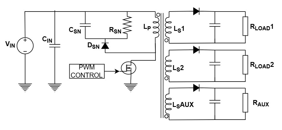
Flyback Converter Design Calculator (DCM, Multi‑Output + Bias)
Primary / Global Inputs
Worst‑case low line
≤ 0.5 typical
Core effective area
Capacitive portion
Secondaries (Outputs)
Choose which output is regulated (via opto or primary‑side regulation). Other outputs will be computed by turns and show error from the target due to rounding. Add 0.5–2% dummy‑load on lightly‑loaded rails for cross‑regulation.
| # | Name | Vout (V) | Iout (A) | Diode drop Vd (V) |
|---|
Bias / Aux Coil
Housekeeping current
Key Results
Transformer & Snubber
Per‑Output Details
Assumptions: DCM at full load; single primary; idealized rectification; loads conduct in their respective demag intervals. Cross‑regulation depends on coupling, leakage, and load distribution — validate with hardware. Consider post‑regulators for tight rails.
How to Use the Flyback Converter Design Calculator
Step‑by‑step guidance for the multi‑output + bias flyback tool (DCM). This covers selecting the regulated rail, sizing transformer turns, estimating cross‑regulation error, snubber picks, and handling negative outputs.
1) Global Inputs
- VIN_min / VIN_max (use true worst case)
- fSW (kHz), DMAX (≤ 0.5 common)
- η (efficiency guess: 0.75–0.9 typical)
- BMAX (T) & Ae (mm²) for core sizing
- Ripple targets: ΔVout (mVpp) capacitive, ESR share (mVpp)
- Margins: VDS +%, VRRM +%; Lleak % for snubber
Primary inductance Lp is set to keep DCM at full load using VIN_min.
2) Outputs Table
- Use + Add Output to create rails (name, Vout, Iout, Vd)
- Enter all loads; the tool sums ΣPout for Lp and Ipk
- Per rail, the tool later computes Ns (rounded), estimated Vout, % error, VRRM, Cout, ESR
3) Choose the Regulated Rail
- Pick the feedback rail in Regulated Output (either a secondary or AUX if using PSR)
- This rail defines the reflected voltage VR = D/(1−D)·VIN_min and the base turns ratio
- Other rails track by turns; expect small deviations after Ns rounding
4) Bias / Aux Coil
- Enter Vaux, Iaux, and Vd
- If using primary‑side regulation, set AUX as the regulated rail
- Otherwise, AUX tracks by turns; the tool shows Ns,aux and estimated Vaux
5) Transformer & Turns
- Tool computes Np from BMAX, Ae, Lp, and Ipk
- For each rail: Ns ≈ Np·(V+Vd)/VR, then rounded to nearest turn
- Estimated Vout and % error are shown post‑rounding (consider post‑reg if tight tolerance)
6) Read the Results
- Lp, Ipk, Ip,rms, VDS (ideal & with margin)
- Per rail: Ns, Vout(est), VRRM (ideal & with margin), Cout for ΔVcap, ESR ≤ ESRmax
- AUX: turns and Vaux(est)
7) Snubber (RCD)
- Estimate Lleak (% of Lp) → tool computes PR, R, C
- Heuristic: Vc,max ≈ 0.1·VDS,spec + VR; tune on bench for critical damping
- Place snubber parts close to MOSFET; use C0G/NP0 for the capacitor
8) Negative Outputs
- In the table, enter the absolute Vout (e.g., 12) and label the rail “−12 V”
- Hardware: reverse diode orientation and dot‑convention so current charges the negative capacitor
- Turns calculation is identical; polarity is set by winding direction & rectifier orientation
Negative rails often need a small dummy load or post‑reg to reduce cross‑reg error.
9) Cross‑Regulation Tips
- Lightly load every rail (0.5–2% rated) to stabilize regulation
- For tight rails, add post‑regulators (LDO/buck) or trim Ns
- Improve coupling (bifilar/tri‑filar, tight layering) to lower leakage & error
Quick Checklist
- ΣPout correct (includes AUX)
- Lp, Ipk within device limits
- VDS & VRRM (with margins) cleared
- Np/Ns rounded and re‑checked for Vout error
- Cout & ESR per rail meet ripple targets
- Snubber tuned; switch‑node ringing acceptable
- Layout: tight primary & secondary loops; single‑point return
- Bench: validate at VIN_max hot and VIN_min cold
FAQ & Tips
Which rail should be regulated?
Choose the most critical rail (by power/tolerance). Others will track by turns; add dummy loads/post‑reg if needed.
My non‑regulated rail is off by a few percent.
Adjust Ns by ±1 turn and re‑check, improve coupling, or add a small post‑regulator.
AUX voltage rises at light load.
Add a small preload resistor, or regulate a main rail and use AUX only for housekeeping.
Snubber runs warm.
Reduce leakage (better winding), retune R/C, or consider an RCD‑Z clamp/active clamp for higher efficiency.
Copy‑Paste Mini Workflow
1) Enter VIN_min/max, fSW, DMAX, η, BMAX, Ae, ripple targets & margins
2) Add all outputs + AUX; pick the regulated rail
3) Read Lp, Ipk, VDS; review Ns, Vout(est), VRRM per rail
4) Adjust Ns or add post‑regulators for tight rails; add dummy loads if needed
5) Size Cout/ESR per rail; tune snubber; validate on bench