
Boost Converter Designer
This professional tool calculates parameters for DC-DC Boost Converters (Step-Up). It determines the minimum Inductance required for Continuous Conduction Mode (CCM) and sizing for output capacitors.
It includes a unique Component Sizing Guide that applies safety margins to help you select robust MOSFETs, Diodes, and Inductors for your SMPS design.
Specs & Margins
InputDerating / Safety
Parasitics
Design Analysis
CCM ModeCommon Boost Configurations
Standard voltage conversion scenarios and typical component requirements.
| Application | Input | Output | Duty Cycle | Switch Rating |
|---|---|---|---|---|
| Li-Ion to USB | 3.7 V | 5.0 V | ~26% | > 10V |
| 12V Bus to 24V | 12 V | 24 V | 50% | > 30V |
| Laptop Charger (Auto) | 12 V | 19 V | 37% | > 25V |
| LED Driver | 24 V | 48 V | 50% | > 60V |
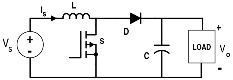
Physics Explained
[Image of boost converter circuit diagram]Component Derating
Using components at 100% of their rating reduces lifespan. A 20-30% safety margin (Derating) is standard engineering practice for SMPS reliability.
RHP Zero
The Right-Half-Plane Zero (RHPZ) is a dynamic instability in boost converters. Your control loop bandwidth must be significantly lower than fRHPZ.
CCM vs DCM
CCM: Inductor current never hits zero (High power).
DCM: Inductor fully discharges every cycle (Low power/Light load).
How to Use
Set Operating Point
Define input/output voltages and load current. Ensure Vout > Vin. The tool assumes a standard non-isolated topology.
Set Safety Margins
Input your desired Voltage and Current margins (e.g., 25%). The Sizing Guide will automatically suggest minimum ratings.
Check Stability
Ensure your control loop crossover frequency is significantly lower than the calculated RHP Zero to prevent oscillation.