
Buck-Boost Converter Designer
Professional design tool for Inverting Buck-Boost Converters. This topology can Step-Up or Step-Down voltage, but the output polarity is reversed (Negative Output).
This calculator determines the required Inductance, analyzes high voltage stress on switches, and checks capacitor RMS current ratings.
Specs & Margins
Input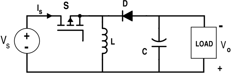
Design Analysis
CCM ModeTopology Stress Comparison
The Buck-Boost topology (Inverting) places significantly higher stress on components compared to standard Buck or Boost converters.
| Feature | Buck | Boost | Buck-Boost (Inv) |
|---|---|---|---|
| Voltage Conversion | Step Down | Step Up | Step Up / Down |
| Output Polarity | Positive (+) | Positive (+) | Negative (-) |
| Switch Voltage Stress | Vin | Vout | Vin + |Vout| |
| Capacitor RMS Current | Input High / Output Low | Input Low / Output High | High on Both |
Physics Explained
Dual Pulsed Current
In Buck-Boost, both Input and Output capacitors see pulsed currents. Both capacitors must be rated for high RMS current (and low ESR) to prevent overheating.
Voltage Stress
The switch and diode must withstand Vin + Vout. This is significantly higher than in Buck or Boost topologies, requiring components with higher breakdown voltage ratings.
RHP Zero
Like the Boost, the Buck-Boost has a Right-Half-Plane Zero that limits bandwidth. Control must be slow (fc << fRHPZ) to remain stable.
How to Use
Set Voltages
Define Vin and the absolute value of Vout. The topology is inverting, but input positive values for calculation.
Check Voltage Stress
Ensure your MOSFET and Diode are rated for at least Vin + Vout plus safety margin.
Capacitor Selection
Buck-Boost requires robust capacitors on both sides. Check the RMS current ratings in the Sizing Guide.