
Time Constant Calculator (RC & RL)
Calculate circuit charge time, transient response, and cutoff frequency.
The Time Constant (τ) represents the speed at which a circuit responds to a change in voltage. It defines the time required to charge a capacitor (or energize an inductor) to 63.2% of its maximum capacity.
This tool supports both RC (Resistor-Capacitor) and RL (Resistor-Inductor) circuits. It generates a Precision Charge Curve to visualize the transient response over time.
Circuit Parameters
Instantaneous Voltage
Dynamic Charge Curve
Live Graph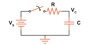
Physics & Formulas
RC Formula
τ = R × C
Time (s) = Resistance (Ω) × Capacitance (F). Measures charging speed.RL Formula
τ = L / R
Time (s) = Inductance (H) / Resistance (Ω). Measures energizing speed.5-Tau Rule
tfull ≈ 5 × τ
A capacitor is considered “fully charged” (99.3%) after 5 time constants.Cutoff Frequency
fc = 1 / (2πτ)
The frequency at which the filter attenuates signal power by half (-3dB).Common Questions
How to Use
Calculate circuit timing in 3 steps.
Select Circuit Type
Toggle between RC (Capacitor) and RL (Inductor) using the buttons at the top.
Enter Values
Input the Resistance and Capacitance/Inductance. Use the dropdowns to select units (e.g., µF, kΩ).
Analyze Transient Response
The tool calculates τ instantly. Use the “At Time (t)” input to find the exact charge percentage at any specific moment.